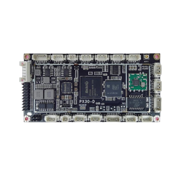
Item NO.:
PX30 PCBAProduct Origin:
ChinaColor:
blackShipping Port:
ShenzhenItem:
PX30 PCBAMOQ:
1Sample:
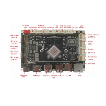
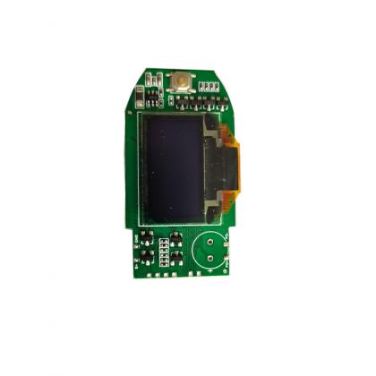
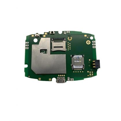
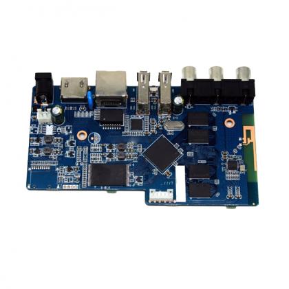
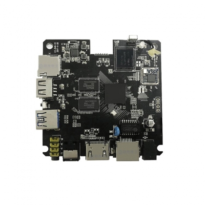
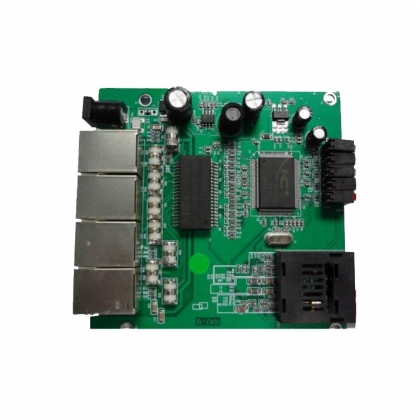
1PX30 Industrial Board Is Used For Advertising Machine Motherboard Supporting Touch Assembly PCBA
Chapter One Product Overview
1.1. Overview
The PX30 Android all-in-one board adopts Rockchip's PX30CORTE-A35 quad-core chip solution.Frequency up to 1.5GHz;
Support Google Android 9.0 operating system; GPU adopts Mali-G31, embedded high-performance 2D acceleration hardware, supports mainstream
Decoding of audio and video formats and pictures; the comprehensive running score is as high as more than 40,000 points.Meet human-computer interaction, play games, and play videos、
Industrial control and other functional requirements; rich on-board interfaces and I/O, rich and flexible connectivity and extensibility, support for commonly used external connections
Equipment; rich interface, stable performance, to meet the requirements of different scenarios;
1.2. Characteristics
High performance: PX30 is a high-power, cost-effective application processor series designed by Rockchip, using a single quad-core
Advanced chip with 64-bit ARMCORTE-A35 core, designed for personal mobile Internet devices and other digital multimedia applications
A high-performance quad-core application processor designed for use.Provides many embedded powerful hardware engines to optimize high-end applications
The performance of the program.The GPU adopts Mali-G31MP2 and supports VC-1, H265/H264, MPEG-1/2/4, VP8
And other multi-format 1080P 60fps video decoding.
High stability: PX30 Android all-in-one board, in terms of hardware and software, adds its own unique technology to ensure product stability
Qualitatively, the final product can be unattended for 7*24 hours.
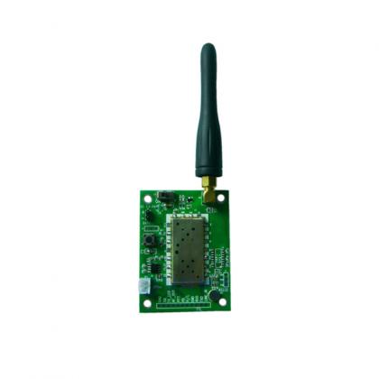
High degree of integration: PX30 Android all-in-one board integrates Ethernet, WiFi, Bluetooth, 4Ω/18W power amplifier, TF card expansion、
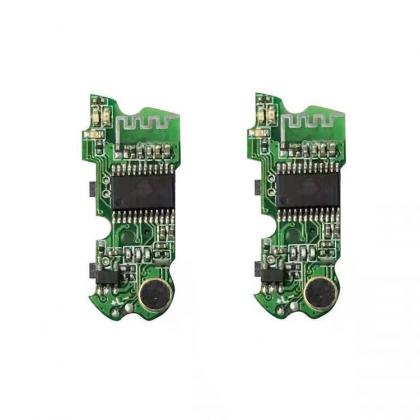
IR remote control function, LVDS, MIPI screen, MIPI camera, microphone, gravity sensing and other functions are greatly simplified
The whole machine design.The ultra-thin motherboard design can make the whole machine design more beautiful.
Rich interfaces: support USB2.0, fill light interface, serial port, I2C interface, GPIO, ADC, etc., can be expanded and more
Many peripheral devices.Can meet common peripherals on the market, such as serial card swipe equipment, printing equipment, audio and video acquisition equipment
Equipment and so on.
System customization: Support Android system optimization and customization, and provide system call interface API reference code.
Chapter 3 List of Basic Specifications and Functions
3.1. Basic hardwarespecifications and functions
3.2. Basic software specifications and functions
|
Operating system |
Android 9.0 |
|
audio |
M P 3 , W M A , W A V , A P E , F L A C , A A C , O G G , M 4 A , 3 G P PAnd other formats |
|
video |
Supports 1080P multi-video decoding of H.265, H.264,VP8,MAV,WMV,AVS, H.263,MPEG4 and other video formats |
|
picture |
Support JPG, BMP, PNG and other image formats to browse and support rotation/slideshow playback/image enlargement function |
|
The system comes with application software |
APK installer, email, calculator, browser, voice recorder, calendar, settings, clock, video player, search, address book, gallery, download, camera, music, resource manager |
|
Language support |
Multi-language |
|
Input method |
Standard Android keyboard, optional third-party input method (Chinese, Korean, Japanese, etc.) |
|
System management |
Original ecological Android system, open root permissions, can be customized for product development |
|
|
Real-time remote monitoring, self-recovery from system crash, unattended for 7*24 hours |
|
|
Support OTA remote upgrade |
|
|
Support wifi display |
|
System watchdog |
Support software watchdog |
3.3. Working and storage environment
|
Operating ambient temperature |
25℃~70℃, recommended -5℃~40℃ |
|
Working environment humidity |
10% ~ 90%, no condensation |
|
Storage temperature |
30 ° C to 75 ° C, recommended for storage at room temperature |
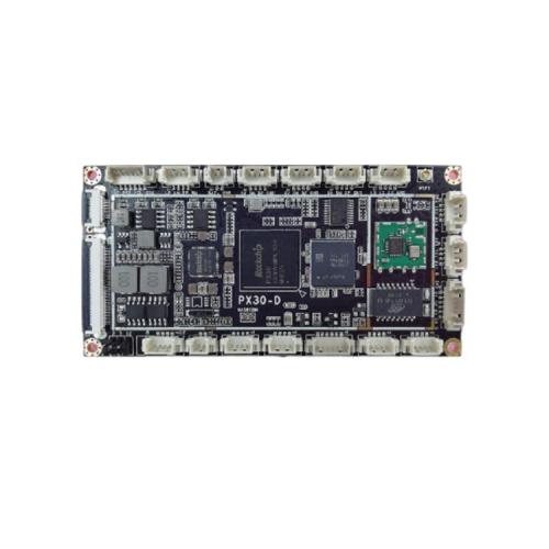
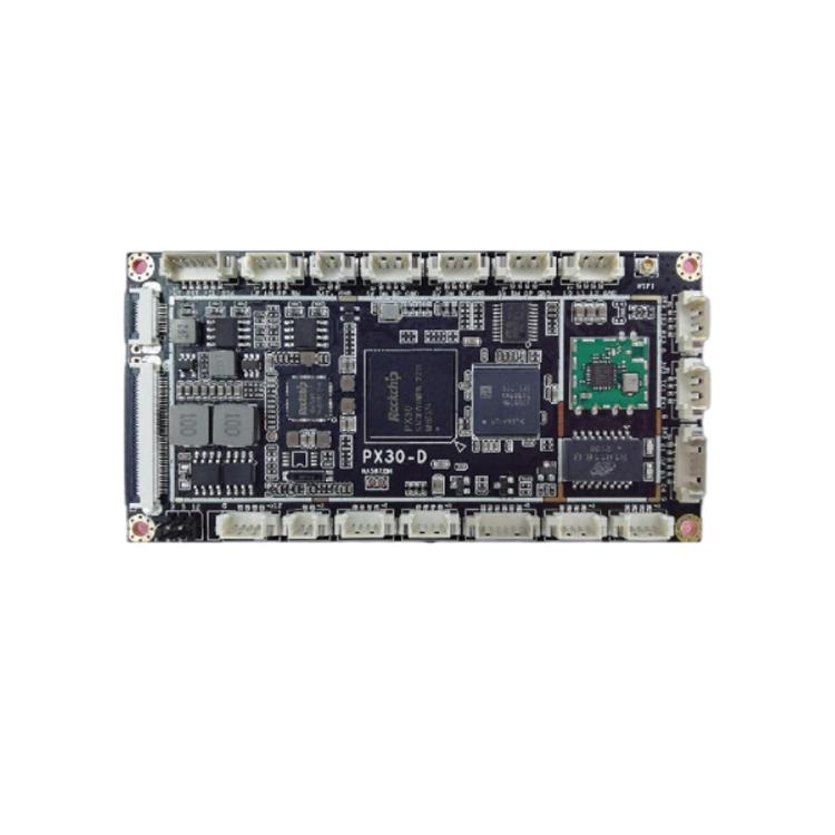
Chapter 4 PCBA Structure
4.1.PCBA size drawing
4.2. Specifications
Motherboard size: 100*50*8.6 mm
Motherboard height: front ≤5mm, back ≤mm
Number of PCB layers: 8 layers
PCB size: 100*50*1.6 mm
PCB color: black
PCB process: Sinking gold
Screw hole specification: φ2mm*4
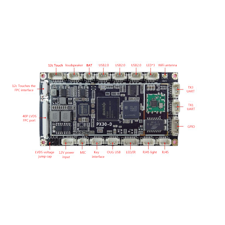
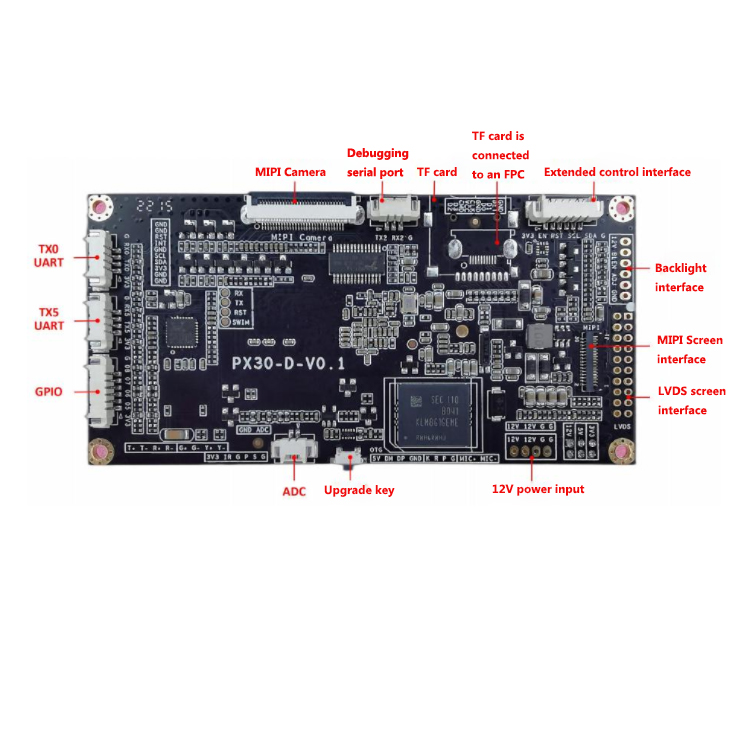
Chapter 5 Interface definition
5.1. Interface description
5.1.1, LVDS FPC screen interface (40PIN/0.5)
|
Serial number |
Definition |
Attribute |
Description |
|
1 |
VCOM |
Power supply |
COM voltage |
|
2 |
VDD |
Power supply |
VDD3.3V |
|
3 |
YDD |
Power supply |
VDD3.3V |
|
4 |
NC1 |
NC |
NC |
|
5 |
Reset |
output |
Reset |
|
6 |
STBYB |
output |
STBYB |
|
7 |
GND |
ground |
ground |
|
8 |
LVDS-D0N |
output |
Negative data output |
|
9 |
LVDS-DOP |
output |
Positive data output |
|
10 |
GND |
ground |
ground |
|
11 |
LVDS-DIN |
output |
Negative data output |
|
12 |
LVDS-D1P |
output |
Positive data output |
|
13 |
GND |
ground |
ground |
|
14 |
LVDS-D2N |
output |
Negative data output |
|
15 |
LVDS-D2P |
output |
Positive data output |
|
16 |
GND |
ground |
ground |
|
17 |
LVDS-CLKN |
output |
Negative data output |
|
18 |
LVDS-CLKP |
output |
Positive data output |
|
19 |
GND |
ground |
ground |
|
20 |
LVDS-D3N |
output |
Negative data output |
|
21 |
LVDS-D3P |
output |
Positive data output |
|
22 |
GND |
ground |
ground |
|
23 |
NC2 |
NC |
NC |
|
24 |
NC3 |
NC |
NC |
|
25 |
GND |
ground |
ground |
|
26 |
NC4 |
NC |
NC |
|
27 |
DIMO |
output |
Backlight CABA control signal |
|
28 |
SELB |
output |
6/8bit mode selection |
|
29 |
AVDD |
Power supply |
AVDD |
|
30 |
GND |
ground |
ground |
|
31 |
LED- |
Power supply |
Backlight negative electrode |
|
32 |
LED- |
Power supply |
Backlight negative electrode |
|
33 |
L/R |
output |
Horizontal mirror |
|
34 |
U/D |
output |
Vertical mirror |
|
35 |
VGL |
Power supply |
Gate OFF Voltage |
|
36 |
CABCEN1 |
output |
CABA H/W enable |
|
37 |
CABCEN0 |
output |
CABA H/W enable |
|
38 |
VGH |
Power supply |
Gate ON Voltage |
|
39 |
LED+ |
Power supply |
Backlight positive electrode |
|
40 |
LED+ |
Power supply |
Backlight positive electrode |
5.1.2, I2C touch FPC interface (10PIN/0.5)
|
Serial number |
definition |
attribute |
description |
|
1 |
GND |
ground |
ground |
|
2 |
GND |
ground |
ground |
|
3 |
3V3 |
Power supply |
3.3V output |
|
4 |
SDA |
Input/output |
ⅡC data |
|
5 |
SCL |
Input/output |
ⅡC clock |
|
6 |
GND |
ground |
ground |
|
7 |
INT |
Input/output |
Interrupt data |
|
8 |
RST |
Input/output |
Reset data |
|
9 |
GND |
ground |
ground |
|
10 |
GND |
ground |
ground |
5.1.3、I2C触摸接口(6PIN/1.25)
5.1.3 I2C touch interface (6PIN/1.25)
|
Serial number |
definition |
attribute |
description |
|
1 |
3.3V |
Power supply |
3.3V output |
|
2 |
INT |
Input/output |
Interrupt data |
|
3 |
RST |
Input/output |
Reset data |
|
4 |
SCL |
Input/output |
IC clock |
|
5 |
SDA |
Input/output |
ⅡC data |
|
6 |
GND |
ground |
ground |
5.1.4、 喇叭输出接口(4PIN/1.25)
5.1.4, horn output interface (4PIN/1.25)
|
Serial number |
definition |
attribute |
description |
|
1 |
LP |
output |
Positive left channel output |
|
2 |
LN |
output |
Positive left channel output |
|
3 |
RP |
output |
Positive output of the right channel |
|
4 |
RN |
output |
Positive output of the right channel |
5.1.5、RTC电池接口(2PIN/1.25)
5.1.5, RTC battery interface (2PIN/1.25)
|
Serial number |
definition |
attribute |
description |
|
1 |
BAT+ |
input |
3V input |
|
2 |
GND |
ground |
ground |
5.1.6、USB-HOST 接口(4PIN/1.25)
5.1.6, USB-HOST interface (4PIN/1.25)
|
Serial number |
definition |
attribute |
description |
|
5V |
Power supply |
5V output |
|
|
2 |
DM |
Input/output |
Data negative |
|
3 |
DP |
Input/output |
Positive data |
|
4 |
GND |
ground |
ground |
5.1.7、USB-HOST 接口(4PIN/1.25)
5.1.7, USB-HOST interface (4PIN/1.25)
|
Serial number |
definition |
attribute |
description |
|
1 |
5V |
Power supply |
5V output |
|
2 |
DM |
Input/output |
Data negative |
|
3 |
DP |
Input/output |
Positive data |
|
4 |
GND |
ground |
ground |
5.1.8、USB-HOST 接口(4PIN/1.25)
5.1.8, USB-HOST interface (4PIN/1.25)
|
Serial number |
definition |
attribute |
description |
|
1 |
5V |
Power supply |
5V output |
|
2 |
DM |
Input/output |
Data negative |
|
3 |
DP |
Input/output |
Positive data |
|
4 |
GND |
ground |
ground |
5.1.9、 补光灯接口(4PIN/1.25)
5.1.9, fill light interface (4PIN/1.25)
|
Serial number |
definition |
attribute |
description |
|
1 |
L0 |
Power supply |
12V voltage output |
|
2 |
LI |
Power supply |
12V voltage output |
|
3 |
L2 |
Power supply |
12V voltage output |
|
4 |
GND |
ground |
ground |
5.1.10、UART 串口接口(4PIN/1.25)
5.1.10, UART Serial port (4PIN/1.25)
|
Serial number |
definition |
attribute |
description |
|
1 |
3V3 |
Power supply |
3.3V output |
|
2 |
TX3 |
output |
send |
|
3 |
RX3 |
input |
receive |
|
4 |
GND |
ground |
ground |
5.1.11、UART 串口接口(4PIN/1.25)
5.1.11 UART Serial Port (4PIN/1.25)
|
Serial number |
definition |
attribute |
description |
|
1 |
3V3 |
Power supply |
3.3V output |
|
2 |
TX1 |
output |
send |
|
3 |
RX1 |
input |
receive |
|
4 |
GND |
ground |
ground |
5.1.12、GPIO 接口(6PIN/1.25)
5.1.12, GPIO interface (6PIN/1.25)
|
Serial number |
definition |
attribute |
description |
|
1 |
3V3 |
Power supply |
3.3V output |
|
2 |
01 |
Input/output |
Default high level |
|
3 |
02 |
Input/output |
Default high level |
|
4 |
03 |
Input/output |
Default high level |
|
5 |
04 |
Input/outpu |
Default low level |
|
6 |
GND |
ground |
ground |
5.1.13、RJ45 接口(4PIN/1.25)
5.1.13, RJ45 interface (4PIN/1.25)
|
Serial number |
definition |
attribute |
description |
|
1 |
T+ |
output |
RJ45 data transmission positive end |
|
2 |
|
output |
RJ45 data transmission negative terminal |
|
3 |
R+ |
input |
RJ45 data receiving positive terminal |
|
4 |
|
input |
RJ45 data receiving negative terminal |
5.1.14、RJ45 灯接口(4PIN/1.25)
5.1.14, RJ45 light interface (4PIN/1.25)
|
Serial number |
definition |
attribute |
description |
|
1 |
G+ |
Power supply |
Positive connection status indicator |
|
2 |
|
Power supply |
Connection status indicator negative |
|
3 |
Y+ |
Power supply |
Positive signal transmission indicator light |
|
4 |
|
Power supply |
Signal transmission indicator light negative electrode |
5.1.15、 遥控和指示灯接口(6PIN/1.25)
5.1.15, remote control and indicator port (6PIN/1.25)
|
Serial number |
definition |
attribute |
description |
|
1 |
3V3 |
Power supply |
3.3V output |
|
2 |
IR |
input |
Infrared signal input |
|
3 |
GND |
ground |
ground |
|
4 |
LEDP |
output |
Power indicator (red) light positive |
|
5 |
LEDS |
output |
System indicator (green) light positive |
|
6 |
GND |
ground |
ground |
5.1.16、 USB-OTG 接口(4PIN/1.25)
5.1.16, USB-OTG interface (4PIN/1.25)
|
Serial number |
definition |
attribute |
description |
|
1 |
5V |
Power supply |
5V output |
|
2 |
DM |
Input/output |
Data negative |
|
3 |
DP |
Input/output |
Positive data |
|
4 |
GND |
Ground |
Ground |
5.1.17、 按键接口(4PIN/1.25)
5.1.17, key interface (4PIN/1.25)
|
Serial number |
definition |
attribute |
description |
|
1 |
K |
input |
Upgrade button/volume+ |
|
2 |
R |
input |
Reset button |
|
3 |
P |
input |
Switch button |
|
4 |
GND |
ground |
ground |
5.1.18、 麦克风接口(2PIN/1.25)
5.1.18, Microphone interface (2PIN/1.25)
|
Serial number |
definition |
attribute |
description |
|
1 |
MIC+ |
input |
MIC positive input |
|
2 |
MIC- |
input |
MIC negative input |
5.1.19、12V 电源输入接口(4PIN/1.25)
5.1.19, 12V power input interface (4PIN/1.25)
|
Serial number |
definition |
attribute |
description |
|
1 |
12V |
Power supply |
12V power supply |
|
2 |
12V |
Power supply |
12V power supply |
|
3 |
GND |
ground |
ground |
|
4 |
GND |
ground |
ground |
5.1.20、LVDS 屏电压跳帽接口(2x3PIN/2.0)
5.1.20, LVDS screen Voltage jump cap interface (2x3PIN/2.0)
|
Serial number |
definition |
attribute |
description |
|
12V |
Power supply |
12V output |
|
|
2 |
LVDS-VDD-IN |
Power supply |
LVDS voltage input |
|
3 |
5V |
Power supply |
5V output |
|
4 |
LVDS-VDD-IN |
Power supply |
LVDS voltage input |
|
5 |
3.3V |
Power supply |
3.3V output |
|
6 |
LVDS-VDD-IN |
Power supply |
LVDS voltage input |
5.1.21、GPIO 接口(6PIN/1.25)
5.1.21, GPIO interface (6PIN/1.25)
|
Serial number |
definition |
attribute |
description |
|
1 |
3V3 |
Power supply |
3.3V output |
|
2 |
05 |
Input/output |
Default high level |
|
3 |
06 |
Input/output |
Default high level |
|
4 |
07 |
Input/output |
Default low level |
|
5 |
08 |
Input/output |
Default low level |
|
6 |
GND |
ground |
ground |
5.1.22、UART 串口接口(4PIN/1.25)
5.1.22, UART Serial port (4PIN/1.25)
|
Serial number |
definition |
attribute |
description |
|
3V3 |
Power supply |
3.3V output |
|
|
2 |
TX5 |
output |
send |
|
3 |
RX5 |
input |
receive |
|
4 |
GND |
ground |
ground |
5.1.23、UART 串口接口(4PIN/1.25)
5.1.23, UART Serial port (4PIN/1.25)
|
Serial number |
definition |
attribute |
description |
|
1 |
3V3 |
Power supply |
3.3V output |
|
2 |
TX0 |
output |
send |
|
3 |
RXO |
input |
receive |
|
4 |
GND |
ground |
ground |
5.1.24、MIPI Camera接口(30PIN/0.5)
5.1.24, MIPI Camera interface (30PIN/0.5)
|
Serial number |
definition |
attribute |
description |
|
1 |
NC |
NC |
NC |
|
VDD28 |
Power supply |
2.8V output |
|
|
3 |
VDD12 |
Power supply |
1.2V output |
|
4 |
VDD18 |
Power supply |
1.8V output |
|
5 |
NC |
NC |
NC |
|
6 |
GND |
ground |
ground |
|
7 |
VDD28 |
Power supply |
2.8V output |
|
8 |
GND |
ground |
ground |
|
9 |
SDA |
Input/output |
IC data |
|
10 |
SCL |
Input/output |
IC clock |
|
11 |
RST |
output |
reset |
|
12 |
PWDN |
output |
PWDN signal |
|
13 |
GND |
ground |
ground |
|
14 |
MLCK |
output |
Clock signal |
|
15 |
GND |
ground |
ground |
|
16 |
DP3 |
output |
Positive data output |
|
17 |
DN3 |
output |
Negative data output |
|
18 |
GND |
ground |
ground |
|
19 |
DP2 |
output |
Positive data output |
|
20 |
DN2 |
output |
Negative data output |
|
21 |
GND |
ground |
ground |
|
2 |
DP1 |
output |
Positive data output |
|
23 |
DN1 |
output |
Negative data output |
|
24 |
GND |
ground |
ground |
|
25 |
CLKP |
output |
Positive data output |
|
26 |
CLKN |
output |
Negative data output |
|
27 |
GND |
ground |
ground |
|
28 |
DP0 |
output |
Positive data output |
|
29 |
DNO |
output |
Negative data output |
|
30 |
GND |
ground |
ground |
5.1.25、 调试串口接口(3PIN/1.25)
5.1.25 Debugging serial port (3PIN/1.25)
|
Serial number |
definition |
attribute |
description |
|
1 |
TX2 |
output |
send |
|
2 |
RX2 |
input |
receive |
|
3 |
GND |
ground |
ground |
5.1.26、TF 卡外接FPC 接口(10PIN/0.5)
5.1.26, TF card external FPC interface (10PIN/0.5)
|
Serial number |
definition |
attribute |
description |
|
1 |
D2 |
Input/output |
TF card signal |
|
2 |
D3 |
Input/output |
TF card signal |
|
3 |
CMD |
Input/output |
TF card signal |
|
4 |
VCC |
Power supply |
3.3V |
|
5 |
CLK |
Input/output |
TF card signal |
|
6 |
GND |
ground |
ground |
|
7 |
D0 |
Input/output |
TF card signal |
|
8 |
D1 |
Input/output |
TF card signal |
|
9 |
DET |
Input/output |
TF card detection |
|
10 |
GND |
ground |
ground |
5.1.27、 扩展控制接口(6PIN/1.25)
5.1.27, extended control interface (6PIN/1.25)
|
Serial number |
definition |
attribute |
description |
|
1 |
3V3 |
Power supply |
3.3V output |
|
2 |
EN |
Input/output |
Control pin EN |
|
3 |
RST |
Input/output |
Control pin RST |
|
4 |
SCL |
Input/output |
IC clock |
|
5 |
SDA |
Input/output |
IC data |
|
6 |
GND |
ground |
ground |
5.1.28、 屏背光接口(6PIN/2.0)
5.1.28, Screen backlight interface (6PIN/2.0)
|
Serial number |
definition |
attribute |
description |
|
1 |
12V |
Power supply |
12V output |
|
2 |
12V |
Power supply |
12V output |
|
3 |
BLEN |
output |
Backlight enabled (5V) |
|
4 |
ADJ |
output |
Backlight brightness adjustment (0~5V) |
|
5 |
GND |
ground |
ground |
|
6 |
GND |
ground |
ground |
5.1.29、MIPI 屏接口(31PIN/0.3)
5.1.29, MIPI screen interface (31PIN/0.3)
|
Serial number |
definition |
attribute |
description |
|
1 |
LED+ |
Backlight power supply |
Backlight positive electrode |
|
2 |
LED+ |
Backlight power supply |
Backlight positive electrode |
|
3 |
LED+ |
Backlight power supply |
Backlight positive electrode |
|
4 |
GND |
ground |
ground |
|
5 |
LED- |
Backlit ground |
Backlight negative electrode |
|
6 |
LED- |
Backlit ground |
Backlight negative electrode |
|
7 |
LED- |
Backlit ground |
Backlight negative electrode |
|
8 |
LED- |
Backlit ground |
Backlight negative electrode |
|
9 |
GND |
ground |
ground |
|
10 |
GND |
ground |
ground |
|
11 |
MiPi-D2P |
output |
Positive data output |
|
12 |
MiPi-D2N |
output |
Negative data output |
|
13 |
GND |
ground |
ground |
|
14 |
MiPi-D1P |
output |
Positive data output |
|
15 |
MiPi-D1N |
output |
Negative data output |
|
16 |
GND |
ground |
ground |
|
17 |
MiPi-CLKP |
output |
Positive data output |
|
18 |
MiPi-CLKN |
output |
Negative data output |
|
19 |
GND |
ground |
ground |
|
20 |
MiPi-DOP |
output |
Positive data output |
|
21 |
MiPi-DON |
output |
Negative data output |
|
22 |
GND |
ground |
ground |
|
23 |
MiPi-D3P |
output |
Positive data output |
|
24 |
MiPi-D3N |
output |
Negative data output |
|
25 |
GND |
ground |
ground |
|
26 |
NC |
NC |
NC |
|
27 |
RESET |
output |
reset |
|
28 |
NC |
NC |
NC |
|
29 |
VDDIO1.8V |
output |
VDD1.8V |
|
30 |
VDD3.3V |
output |
VDD3.3V |
|
31 |
VDD3.3V |
output |
VDD3.3V |
5.1.30、LVDS 屏接口(2x10PIN/2.0)
5.1.30, LVDS screen interface (2x10PIN/2.0)
|
Serial number |
definition |
attribute |
description |
|
1 |
POWER |
Power supply |
Screen power output 3.3V/5V/12V specific voltage is selected by the jumper
|
|
2 |
POWER |
Power supply |
|
|
3 |
POWER |
Power supply |
|
|
4 |
GND |
ground |
ground |
|
5 |
GND |
ground |
ground |
|
6 |
GND |
ground |
ground |
|
7 |
LVDS-DON |
output |
Negative data output |
|
8 |
LVDS-DOP |
output |
Positive data output |
|
9 |
LVDS-DIN |
output |
Negative data output |
|
10 |
LVDS-DIP |
output |
Positive data output |
|
11 |
LVDS-D2N |
output |
Negative data output |
|
12 |
LVDS-D2P |
output |
Positive data output |
|
13 |
GND |
ground |
ground |
|
14 |
GND |
ground |
地 |
|
15 |
LVDS-CLKN |
output |
Negative data output |
|
16 |
LVDS-CLKP |
output |
Positive data output |
|
17 |
LVDS-D3N |
output |
Negative data output |
|
18 |
LVDS-D3P |
output |
Positive data output |
|
19 |
NC |
NC |
NC |
|
20 |
NC |
NC |
NC |
5.1.31、12V 电源输入接口(4PIN/2.0)
5.1.31, 12V power input port (4PIN/2.0)
|
Serial number |
definition |
attribute |
description |
|
1 |
GND |
ground |
ground |
|
2 |
GND |
ground |
ground |
|
3 |
12V |
Power supply |
12V power supply |
|
4 |
12V |
Power supply |
12V power supply |
5.1.32、ADC 转换接口(2PIN/1.25)
5.1.32, ADC conversion interface (2PIN/1.25)
|
Serial number |
definition |
attribute |
description |
|
1 |
ADC |
input |
ADC input |
|
2 |
GND |
ground |
ground |
5.2、 其余标准接口以及功能
5.2. Other standard interfaces and functions
|
name |
Seat specifications |
description |
|
TF card holder |
Standard TF card holder |
Support up to 128GB |
|
Upgrade button |
Non-self-locking button |
UBOOT button |
|
WIFI antenna holder |
IPEX-1 generation male |
WIFI/Bluetooth antenna |
Chapter VI Precautions
▲Please wear electrostatic protection tools such as electrostatic bracelets when touching the motherboard (have a good grounding);
▲Do not operate with live assembly, wiring, etc.;
▲Please check the definition of the motherboard interface and the definition of the peripheral interface, there can be no wrong connection or reverse connection.;
▲Please use M2 flat round head screws to fix the motherboard. Do not use countersunk heads or screws with larger specifications; be careful to avoid deformation and bending of the motherboard when twisting the screws.;
▲Pay attention to the level matching of IO port, serial port, enable pin, etc.;
▲Pay attention to the power of the external screen. If the power is large, please consider external power supply.;
▲Pay attention to the overall power of the product and choose a power supply with sufficient power;


 English